2PC Ball Valve full-bore AISI316/CF8M PTFE seats and seals DN15-150 (G1/2" - G6") PN40 up to DN50; PN16 in DN65-150 flanged end ABRA-BV41 with direct mounting pad ISO top flangeDesign decisions, long production experience and strict quality control provide ball valves ABRA-BV the best possible standard tightness - leakage rate corresponding to Rate A according ISO 5208 and GOST54808 and GOST 9544
| Materials specification: description. |
|
|
Price-list and available stock rest
2PC Ball Valve full-bore AISI316/CF8M PTFE seats and seals DN15-150 (G1/2" - G6") PN40 up to DN50; PN16 in DN65-150 flanged end ABRA-BV41:
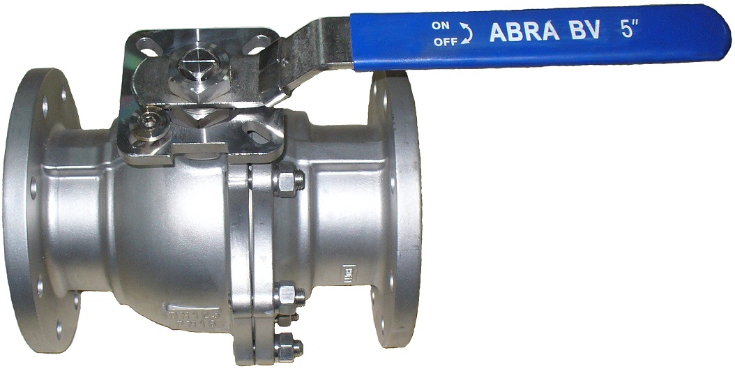
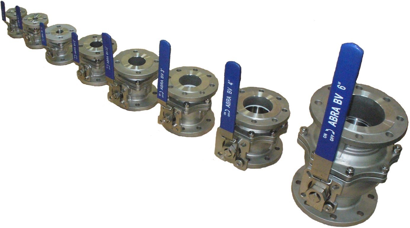
|
Main technical data:
- Maximum steam working pressure 8 bar
- Maximum working temperature 180 °C
- Maximum short time temperature 200 °С
- Hydraulic test in cold water 24/64 bar
Main fields of application - the valve is used as shut-off (on-off) in the following applications:
- Any systems with the following working medias:
- water including seawater, technical, potable, drinking, district heating water, distilled, purified e.t.c.
- salt brines, salt liquors, saline solutions; salt solutions
- water steam (up to 8 bar),
- air, compressed air and neutral gases,
- natural gas, Freons, cooling agents - gaseous
- alcohols, acetic acid (vinegar, ethanoic acid, spirit of verdigris, acetous acid), pure, mixes and solutions
- antifreezes including water glycol mixtures,
- ammonia (hydrogen nitride),
- moderate aggressive acids
- all bases and alkali liquors
- light and heavy petroleum products
- other medias corresponding to material properties
- cold water supply
- hot water supply
- district heating with any standard heat carrier (including antifreezes and non-freezing solutions)
- steam lines up to 200°C,
- condensate loops and lines,
- technical water supply,
- neutral and noble gas pipelines including natural gas,
- water treatment and water intake,
- mineral and synthetic oils transportation e.t.c.
|
|
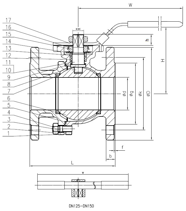
Outline drawing of ball valve ABRA-BV-41 flange ends (sizing is in the table below):
|
Ball valve symbols for piping and instrumentation diagram (P&ID):
|
Dimentions, technical characteristics, weight, Kv and Cv - ball valve ABRA-BV-41 PN40 up to DN50; PN16 in DN65-150 flanged end. Dimentions in mm. Table
DN |
15 |
20 |
25 |
32 |
40 |
50 |
65 |
80 |
100 |
125 |
150 |
| 1/2" |
3/4" |
1" |
1 1/4" |
1 1/2" |
2" |
2 1/2" |
3" |
4" |
5" |
6" |
| PN |
40 |
16 |
| Temperature range: |
Maximum short time temperature 200 °C,
Minimal ambient temperature - 60 °C |
| Code |
ABRA-BV41-
-Q41F-DIN-
-2G-015 |
ABRA-BV41-
-Q41F-DIN-
-2G-020 |
ABRA-BV41-
-Q41F-DIN-
-2G-025 |
ABRA-BV41-
-Q41F-DIN-
-2G-032 |
ABRA-BV41-
-Q41F-DIN-
-2G-040 |
ABRA-BV41-
-Q41F-DIN-
-2G-050 |
ABRA-BV41-
-Q41F-DIN-
-2G-065 |
ABRA-BV41-
-Q41F-DIN-
-2G-080 |
ABRA-BV41-
-Q41F-DIN-
-2G-100 |
ABRA-BV41-
-Q41F-DIN-
-2G-125 |
ABRA-BV41-
-Q41F-DIN-
-2G-150 |
| ød, mm |
15 |
20 |
25 |
32 |
40 |
50 |
65 |
80 |
100 |
125 |
150 |
| øg - height of flange raised face, mm |
45 |
54 |
65 |
78 |
88 |
102 |
122 |
138 |
158 |
188 |
212 |
| f - height of flange raised face, mm |
2 |
2 |
2 |
2 |
2 |
3 |
2 |
2 |
2 |
2 |
2 |
| øk - PCD, pitch-circle diameter, mm |
65 |
75 |
85 |
100 |
110 |
125 |
145 |
160 |
180 |
210 |
240 |
| diameter and qnt. of flage drillings, mm |
4хø14 |
4хø14 |
4хø14 |
4хø18 |
4хø18 |
4хø18 |
4хø18 |
8хø18 |
8хø18 |
8хø18 |
8хø22 |
| øD - outside flange diameter, mm |
95 |
105 |
115 |
140 |
150 |
165 |
185 |
200 |
220 |
250 |
285 |
| b - thickness of flange, mm |
14 |
16 |
16 |
16 |
16 |
17 |
16 |
18 |
18 |
20 |
20 |
| L - installation length, mm |
115 |
120 |
125 |
130 |
140 |
150 |
170 |
180 |
190 |
325 |
350 |
| Н - installation height (from pipe axis), mm |
75 |
80 |
95 |
110 |
135 |
142 |
157 |
183 |
195 |
290 |
308 |
| h, mm |
11 |
11 |
11 |
11 |
16 |
18 |
19 |
20 |
24 |
32 |
37 |
| W -handle, mm |
130 |
130 |
150 |
180 |
200 |
230 |
250 |
280 |
320 |
700 |
800 |
| KxK, mm, squire |
9х9 |
9х9 |
11х11 |
11х11 |
14х14 |
14х14 |
17х17 |
17х17 |
22х22 |
22х22 |
27х27 |
| М12х1,5 |
М14х1,5 |
М18х1,5 |
М22х1,5 |
М30х2 |
М36х2 |
| Кv, m3/h (Cv=1,17 Kv) |
22,3 |
42,8 |
80,5 |
102,8 |
222,8 |
411,3 |
642,7 |
1114,0 |
1970,0 |
3856,0 |
4727,0 |
| Weight, kg |
2,380 |
2,800 |
3,900 |
5,600 |
7,100 |
8,900 |
12,100 |
15,600 |
20,300 |
34,200 |
46,800 |
| ISO5211/5210 |
F03/F04 |
F03/F04 |
F04/F05 |
F04/F05 |
F05/F07 |
F05/F07 |
F07/F10 |
F07/F10 |
F10/F12 |
F10/F12 |
F10/F12 |
| ISO PCD min A / number of holes |
36/M5x4 |
36/M5x4 |
42/M5x4 |
42/M5x4 |
50/M6x4 |
50/M6x4 |
70/M8x4 |
70/M8x4 |
102/M10x4 |
102/M10x4 |
102/M10x4 |
| ISO PCD max B / number of holes |
42/M5x4 |
42/M5x4 |
50/M6x4 |
50/M6x4 |
70/M8x4 |
70/M8x4 |
102/M10x4 |
102/M10x4 |
125/M12x4 |
125/M12x4 |
125/M12x4 |
| Torque, N*m, full differential pressure drop* |
7 |
14 |
23 |
31 |
38,5 |
55 |
66 |
77 |
176 |
240 |
380 |
| *After some rest period the starting torque can be 1,5 - 2 higher then pointed in the table |
|
Connection flanges standards :
| STANDARD |
Notes |
Suitable types to that standard |
PN for connection flanges |
DN for connection flanges |
| EN 1092-1 |
Flange coupling dimensions and sealing surfaces - "new" EU flange standard |
Form A, Form B (B1 and B2) - for sealing surface (common "flat" flanges ) Type - all types if Form as above |
The same as DN of ABRA strainer |
The same as DN of ABRA strainer |
| DIN 2526 |
Flange coupling dimensions and sealing surfaces - "old one" |
Form A, B, C, D, E (common "flat" flanges ) |
| GOST 33259, GOST Р 54432 |
Flange coupling dimensions and sealing surfaces - new Russian flange standards |
All types (Type 01,Type 02, Type 03, Type 04, Type 11, Type 21), Forms only A and B. In DN65 better to take Range1 flange according GOST33259, because it has 4 holes the same as our strainer has. If you take Range 2, you find 8 holes - can be used but not looking nice. (common "flat" flanges ) |
The same as DN of ABRA strainer |
| GOST 12815 |
Flange coupling dimensions and sealing surfaces - "USSR old one" |
Variant 1, range 1, range 2 for all DN, but for DN80. In DN80 better to take Range 1 flange to that GOST , because it has 8 holes the same as our strainer has. If you take Range 2, you find 4 holes - can be used but not looking nice. (common "flat" flanges ) |
Construction - ball valve ABRA-BV-41 PN40 up to DN50; PN16 in DN65-150 flanged end:
| N |
Description |
QNT |
Material |
| 1 |
Body |
1 |
Stainless steel Grade CF8M = AISI/SAE 316 = W.-nr.1,4401 = DINX5CrNiMo17-12-2 = BS316S16 =EN 58J = AFNOR Z6CND17.11 = UNI X5CrNiMo1712 = UNE F.3543 = SS2347 = GB 0Cr17Ni11Mo2= JIS SUS 316 = GOST03Х17Н14М2 |
| 2 |
Body Bonnet |
1 |
Stainless steel AISI/SAE SS 316. Grade CF8M |
| 3 |
Bolt |
4 |
Stainless steel AISI/SAE SS 304 = JIS SUS304 = W.-nr.1.4350 = DIN X5CrNi189 = BS 304S11 = EN 58E = AFNOR Z6CN18.09 = UNI X5CrNi1810 = UNE F.3551 = UNE F.3541 = UNE F.3504 = SS 2332 = GB OCr18Ni9 |
| 4 |
Nut |
4 |
Stainless steel AISI/SAE SS 316. Grade CF8M |
| 5 |
Gasket |
2 |
PTFE |
| 6 |
Ball |
1 |
Stainless steel AISI/SAE SS 316. Grade CF8M |
| 7 |
Seat |
2 |
PTFE |
| 8 |
Stem |
1 |
Stainless steel AISI/SAE SS 316. Grade CF8M |
| 9 |
Washer |
1 |
PTFE |
| 10 |
Spring |
2 |
Stainless steel AISI/SAE SS 304 = Grade CF8 |
| 11 |
Bearing ball |
2 |
Stainless steel AISI/SAE SS 304 = Grade CF8 |
| 12 |
Stem packing |
1 |
PTFE |
| 13 |
Packing |
1 |
Stainless steel AISI/SAE SS 304 = Grade CF8 |
| 14 |
Spring washer |
1 |
Stainless steel AISI/SAE SS 304 = Grade CF8 |
| 15 |
Nut |
2 |
Stainless steel AISI/SAE SS 304 = Grade CF8 |
| 16 |
Spring washer |
1 |
Stainless steel AISI/SAE SS 304 = Grade CF8 |
| 17 |
Handle |
1 |
Stainless steel AISI/SAE + PVC |
|
Pressure / Temperature diagram for ball valve ABRA-BV-41 flanged end:
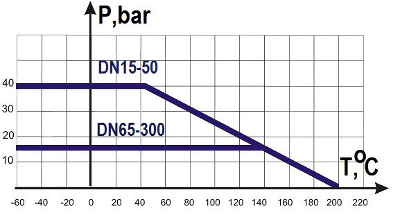
Diagram defines working pressure/tempetarure range ball valve ABRA-BV-41 PN40 up to DN50; PN16 in DN65-150 flanged end |
Installation and maintenance instruction for 2PC ball valve ABRA-BV41 Flange End:
- General.
- The valve should be installed only by person who has enough experience, carefully read the following instruction and got appropriate safety training for that kind of work.
- Before mounting you should check the valve for transportation or storage damage. If you find that you should stop mounting until you get Seller's approval.
- Special note for installation of valves with electrical actuators.
- Before installation the valve and the actuator should be set-up properly for for combined operation as it demanded according to actuator producer's manual:
- Check the assembly or assemble valve and actuator;
- While mounted in any orientation but for strictly vertical the actuator should have own supporting structure undependable from the valve;
- Installation of actuator below the valve is strongly not recommended;
- Set up end position limit switches of the actuator for "On" and "Off" and check safety torque limit switches of the actuator;
- Make few cycles of opening and closing of the valve with manual gear of actuator;
- If manual operation ; was well, then you should make proper connection to electricity and make few cycles of opening and closing of the valve automatically. Only after that if operation is normal you can mount the valve to the pipeline.
- Mounting.
- You should obligatory follow "General Installation and Commissioning demands"
- Delete plastic plugs before mounting.
- Before mounting consider hazardous liquids or gases in the pipeline i.e. - what is in the pipeline or what may have been in the pipeline at some previous time. Consider: flammable materials, substances hazardous to health, extremes of temperature.
- Before mounting consider hazardous environment around the product i.e. - Consider: explosion risk areas, lack of oxygen (e.g. tanks, pits), dangerous gases, extremes of temperature, hot surfaces, fire hazard (e.g. during welding), excessive noise, moving machinery. Consider the effect on the complete system of the work proposed. Will any proposed action (e.g. closing isolation valves, electrical isolation) put any other part of the system or any personnel at risk? Dangers might include isolation of vents or protective devices or the rendering ineffective of controls or alarms. Ensure isolation valves are turned on and off in a gradual way to avoid system shocks. Ensure that any pressure is isolated and safely vented to atmospheric pressure. Consider double isolation (double block and bleed) and the locking or labelling of closed valves. Do not assume that the system has depressurized even when the pressure gauge indicates zero. Allow time for temperature to normalize after isolation to avoid the danger of burns and consider whether protective clothing (including safety glasses) is required.
- Before starting work ensure that you have suitable tools and/or consumables available. Use only genuine ABRA replacement parts. Consider whether you and/or others in the vicinity require any protective clothing to protect against the hazards of, for example, chemicals, high/low temperature, radiation, noise, falling objects, and dangers to eyes and face.
- Ball valve can be installed to the pipe in any orientation.
- Ball valves could be installed in any space direction on the pipeline.
- Before installation, the pipe must be cleaned. If necessary, valves must be cleaned from dirt and dust too.
- During installation in the pipeline, flanges of the pipeline must be exactly parallel to flange connections of the valve.
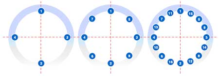
- Flange connection screws are tightened with a torque spanner (Torques according to EN921 - 934 or ISO4732, 4032, 4017 etc.) Tighten the screws in a crosswise sequence. Flanges rods or bolts should be tightened in evenly cross-cross way in three or four passes as shown on the picture:
 - If tightening load in flange connection is weakening due to relaxation in gasket or fixture, or in case when technological process is very cyclic in pressure or temperature the additional tightening of flange connection could be necessary. In most heavy cases (very-very rare) using strong cap washers can help.
- Maintenance.
- The ball valve should be checked visually not less than once per year or more times if that is necessary according to ambient conditions or/and frequency of operations.
- To avoid trim jam the valve should be run the cycle "fully open"/"fully closed" not less than once every 6 month.
- No special treatment is needed for all lifetime of the valve.
- Transportation and Storage.
- Storage and transportation should be without shocks at temperature range: -60…+65°С.
- No parts or objects are allowed to be placed into ball valve ABRA-BV41.
- The valve should be kept in clean and weatherproof placements.
- During transportation ball valve ABRA-BV41 should be properly protected from damage.
- Attention!
- Don't touch valve in operation due to the possible dangerous temperature.
- Before service or/and mounting works you must ensure that the valve is not under the pressure and don't have dangerous temperature.
- Never delete marking from the valve.
- Guarantee.
- Guarantee is 12 month from installation but not more than 18 month from shipment if all demands of this manual are fulfilled.
- Customers and stockists are reminded that under EC Health, Safety and Environment Law, when returning products to ABRA they must provide information on any hazards and the precautions to be taken due to contamination residues or mechanical damage which may present a health, safety or environmental risk. This information must be provided in writing including Health and Safety data sheets relating to any substances identified as hazardous or potentially hazardous.
|
|


